
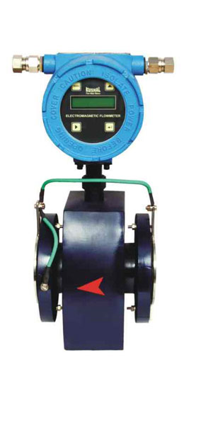
K-01 are micro-controller based full bore type electromagnetic water flow meter specially used for various industrial applications. These flow transmitters accurately measures the flow rate of conductive liquids & slurries in closed pipes. Due to simple & rigid design the flow transmitter is an obstruction less & maintenance free instrument in place of conventional mechanical flow measuring device. The use of 'Pulsed DC' technology offers highest ability & better measuring accuracy in the form of electrical signal 4-20 mA DC linearly proportional to volumetric flow. The instrument is based on Faraday's law of electro-magnetic induction. A magnetic field is generated by the instrument in the flow tube. The fluid flowing through this magnetic field generates a voltage that is proportional to the flow velocity. Corresponding electrical output is provided with respect to measuring voltage.
| Media | Liquid (Conductive) |
| Conductivity | > 5µs/cm |
| Viscosity | 200 cp max |
| Line Size | 15 NB to 2500 NB |
| Excitation | Pulsed DC Coil |
| Type of Output | 1) 40 to 20 mA DC, Isolated 2) Pulse |
| Display | 16x2 LCD - 4 digit for Flow Rate Indication & 8 digit for Totalised Flow |
| Calibration | As per requirement (Factory Calibrated) |
| Accuracy | +/- 0.5% F. S.(For 20 to 100% Flow) |
| Linerity | +/- 0.5% |
| Repeatability | +/- 1% |
| Process Temperature | 70°C Rubber/150°C PTFE |
| Communication Port | On Demand |
| Process Pressure | 16 kg / cm² max |
| Material of construction | Lining - Rubber / PTFE (Teflon), Flange - CS / MS / SS, Electrode - SS 316L / Hastalloy C / Platinum Coil Housing - MS / SS304 |
| Power Supply | 1) 24 V DC, External 2) 90-250 V AC, 50 Hz |
| Power Construction | < 10VA |
| Isolation | 1.4 KV between Input, Output & Power Supply |
| Response Time | < 100mSec |
| Temperature Coefficient | +/- 0.1 % per OC |
| Transmitter Enclosure | Flame-proof, IP-65,IP-67,IP-68, IIA, IIB CMRI certified |
| Process Connections | ASA 150, flanged \, as per table B 16.5 |
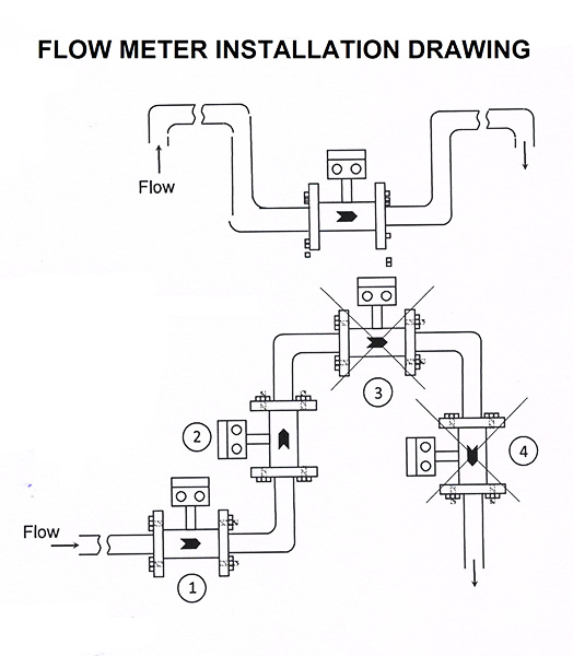
| Mounting | In-Line (Horizontal OR Vertical) |
| Operating Conditions | Temperature 0 to 55°C / Humidity 5 to 95% on condensing |
| Master Size | L (mm) |
W (mm) |
H (mm) |
FD (mm) |
Flow Range | |
| Velocity = 1 m/s | Velocity = 6 m/s | |||||
| 15NB | 150 | 100 | 180 | 200 | 0.64 | 3.82 |
| 20NB | 150 | 100 | 180 | 200 | 1.13 | 6.78 |
| 25NB | 150 | 100 | 180 | 200 | 1.77 | 10.6 |
| 32NB | 180 | 100 | 210 | 200 | 2.90 | 17.4 |
| 40NB | 180 | 100 | 210 | 200 | 4.52 | 27.14 |
| 50NB | 180 | 100 | 210 | 200 | 7.07 | 42.41 |
| 65NB | 185 | 100 | 220 | 200 | 11.95 | 71.68 | 80NB | 207 | 100 | 240 | 200 | 18.10 | 108.87 |
| 100NB | 250 | 150 | 274 | 250 | 28.27 | 169.65 |
| 125NB | 280 | 175 | 300 | 250 | 44.18 | 365.07 |
| 150NB | 320 | 175 | 330 | 300 | 63.62 | 381.7 |
| 200NB | 380 | 175 | 390 | 350 | 113.09 | 678.58 |
| 250NB | 420 | 244 | 440 | 450 | 176.7 | 1060.3 |
| 300NB | 520 | 250 | 520 | 500 | 254.46 | 1526.8 | 350NB | 520 | 250 | 520 | 550 | 346.35 | 2078.2 | 400NB | 520 | 250 | 520 | 600 | 452.38 | 2714.3 | 450NB | 627 | 623 | 632 | 698 | 572.54 | 3435.3 | 500NB | 679 | 623 | 686 | 768 | 706.84 | 4241.2 | 600NB | 770 | 818 | 772 | 918 | 1017.84 | 6107.04 |
All dimensions are indicative dimensions.


